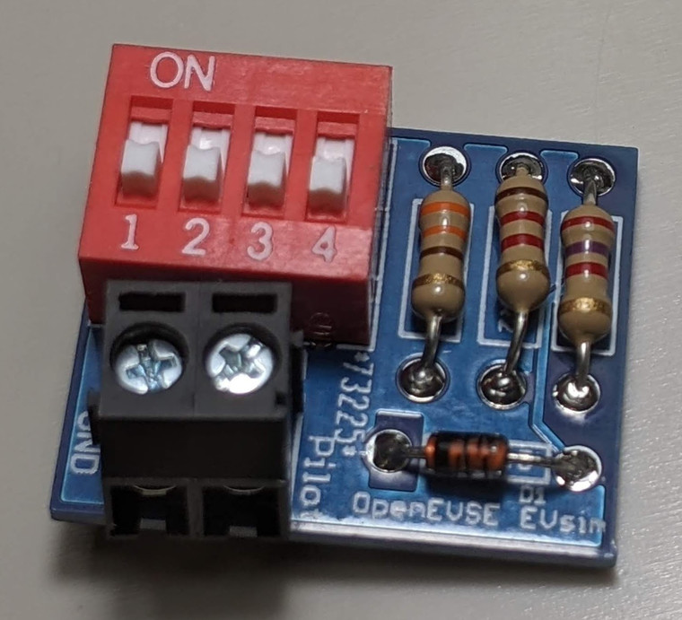
PCB component kit (soldering required) to simulate an EV connecting via J1772. Very useful for EVSE development and testing.
-
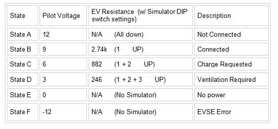
EVSE states can be tested with a few resistors and a diode, and EV Simulator or an EVSE Tester. After a successful Power on Self Test OpenEVSE should enter State A - Ready and the LED/LCD should be Green.
-
State B - EV Connected. Connect 2.74k resistance plus a diode from Pilot to ground. OpenEVSE display should display "EV Connected" and LED/LCD should turn Yellow. (OpenEVSE Sim - 1 on)
-
State C - Charging. Connect 882 ohm resistance plus a diode from Pilot to ground. OpenEVSE display should display "Charging" and LED/LCD should turn Blue. (OpenEVSE Sim - 1 on + 2 on)
-
State D - Ventilation Required. Connect 246 ohms resistance plus a diode from Pilot to ground. OpenEVSE display should display "EVSE ERROR - VENT REQUIRED" and LED/LCD should turn Red. (OpenEVSE Sim - 1 on + 2 on + 3 on)

Included
- EV Simulator PCB (unpopulated)
- Component Kit (soldering assembly required)


